Elements of the building component
In the geometric model used by AnTherm to represent a building component, a single rectangular region or volume in space which is defined as "filled" with one homogeneous material is referred to as an element. Building materials are defined by name (e.g. "concrete masonry unit") and thermal conductivity λ [W/mK].
For a two dimensional case it will be a rectangle parallel to coordinate
system axes. The rectangle (a two dimensional interval) is specified
geometrically by its extents on two coordinate axes - x1 to x2
and y1 to y2 - thus by entering four such
coordinates the rectangular element is defined.
For a three dimensional case the input of further interval dimension is required
- z1 and
z2 are either provided explicitly or they result from the
ordering and thickness of 3D layers.
If two such elements share the same region in space and thus they overlap, the element entered later "displaces" preceding elements (or any parts thereof).
Spaces at boundaries of a component are defined as "air-filled" elements. The air is characterised by the surface resistance Rs [m²K/W] (or the surface heat transfer coefficient α [W/m²K]) appropriate to a designated situation (e.g. "exterior", "interior/along glass", etc.). A single space must later be assigned one, unique temperature condition (in the evaluation branch).
The necessary information about material and space surface properties can be found in standard literature on this topic. This information should be at hand before actually sitting down to work with the program.
Heat sources are defined by an element overlapping one or many other material elements - the name of the heat source is used to identify it (a heat source to which no power is assigned in the evaluation stage is treated just as any other non-emanating building material).
See also: Element type (kind/type of a element)
The definition of a component is provided by the entry of an ordered sequence of elements - these are stored into an element list providing the order of element overlapping.
An example shall show the definition of elements to build a simple component - walls surrounding a space. For the sake of simplicity any openings are not concerned and we assume walls to be homogenous (built of one material).
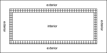
Entry of the component including all surrounding spaces is done in the most
efficient way by starting the input by the entry of the exterior space (exterior
air) rectangle. Any arbitrary size of the rectangle shall be chosen - it is
sufficient if it extends beyond the exterior of walls which itself surround the
interior space.
Following the entry of the exterior space the wall material rectangle is entered
at its exact (exterior) dimensions. Finally, the third element, the interior
space is entered - this results in overwriting the
partial region of the earlier entered material element. The entry is finished.
Of course one could enter the model in some different (circuitous) way: all
three different part types - exterior air, material and the interior air -
could be entered as non overlapping rectangles. This would require much higher
number of elements to be entered however.
Size reduction and adiabatic Cut-Off planes
Although entire buildings can also be evaluated by AnTherm, most practical applications will not be so global in nature. Usually only spatially limited problem zones need be scrutinised. Such a problem zone is typically a structural detail or region which could prove thermally critical.
 Since
thermal bridges are characterised by two- and three-dimensional heat flow
patterns, regions of a building structure in which heat is expected to flow
one-dimensionally (i.e. perpendicular to material surfaces) are generally of
little interest in using AnTherm.
Since
thermal bridges are characterised by two- and three-dimensional heat flow
patterns, regions of a building structure in which heat is expected to flow
one-dimensionally (i.e. perpendicular to material surfaces) are generally of
little interest in using AnTherm.
Therefore such regions may be eliminated from the model to be considered without
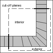
affecting any relevant results. The outer boundary of the region to be analysed
is defined by cut-off planes. These planes are idealised as a non-conducting
surface and should therefore be placed parallel to the direction of heat flow in
a region where one-dimensional heat flow can be assumed.
Just where to optimally draw the cut-off planes - the nearest regions of a problem zone where heat can be expected to flow reasonably normal to planar component surfaces - is initially an educated guess, which may, of course, be subject to revision upon evaluation.
To reference the earlier example the input shall be accomplished in the same manner - at first the exterior space is entered followed by the material rectangle later excavated again with the interior space rectangle. The most important difference to the example above is in that the boundary of the component is only partly covered by space surfaces. The other parts of the boundary (emphasized in bold) are cut-off planes implicitly resulting from the arbitrary user choice to cut the thermal heat bridge at such boundaries, thus inhibiting the heat flow completely (the normal component of heat flux through a cut-off plane is nullified). In this example placing cut-off planes far enough from the corner will be sufficient.
One can also draw upon qualitative characteristics inherent in the geometry of a given object to limit the region to be modelled. Particularly axes of local symmetry in a building component, which can be safely assumed to coincide with planes parallel to heat flow, should be used to cut down the size of a model wherever possible.
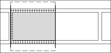
If the model shown in the image above is thought to continue to the left also two types of symmetries can be identified. These are not only the geometrical symmetries, but also the symmetry of temperature distribution which can be expected easily. Due to such symmetry there will be no heat flow through such line. The analysis of such model could be reduced to the area between the two symmetry lines.
See also: The Component