Import of DXF file - Requirements
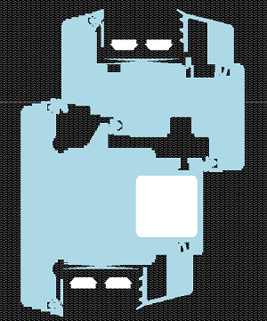
If there is a construction available as a DXF file (e.g. created with AutoCAD® or other CAD application), it can be easily imported and used as a template for creation of a two dimensional component model. Only specifically prepared DXF files can be imported. Only if a DXF file conforms to specific criteria it can be imported into AnTherm.
Below you will find all requirements to follow when creating DXF file which shall be imported to AnTherm.
Attention: AnTherm 8.132
In the new version the DXF import function was enhanced. Now slopes and roundings are imported too.
Regarding the preparation of 2D projects:
- Polylines no longer have to be axis-parallel.
- Simple lines will also be used if they can be combined to polylines.
- It is also possible to use circles, ellipses and arcs.
- Polylines whose layer name starts with "Space" or "Raum" are automatically interpreted as space elements.
The other requirements are like in previous versions (read on). Note: We do not support hatches!
Requirements related to contents of DXF file
The application converts contents of a DXF file into a building component. The substantial characteristics of a building model is described in terms of unique assignment of heat conductivity to specific areas of the construction. This information is usually not entered within CAD input. Therefore the DXF file prepared for the import must rigorously follow some stringent rules.
With regards to the contents of a DXF file following applies:
- Only polylines are read. Any different content of DXF file (lines,
points, labels, blocks, hatches etc.) will be skipped during reading.
-
 Only closed polylines with segments parallel to axes are
processed. Any polyline containing sloped segments, as well as polylines not
declared as closed, will be dropped. (Exception: If the first and last
point of an open polyline coincide exactly by their coordinates, the
application will implicitly close the polyline and consider for further
processing.)
Only closed polylines with segments parallel to axes are
processed. Any polyline containing sloped segments, as well as polylines not
declared as closed, will be dropped. (Exception: If the first and last
point of an open polyline coincide exactly by their coordinates, the
application will implicitly close the polyline and consider for further
processing.)
Hint: Polylines within DXF file shall not self intersect! Evaluation of self intersecting polylines will result in unexpected results.
- Assignments to layers, line types and colours of polylines will
interpreted specifically by the application.
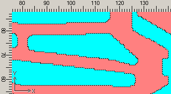
Polylines assigned same layer number will be interpreted as belonging together in such a way, that areas surrounded by them are filled with same material (hence have same thermal conductivity). The layer name will be used as name of material.
Analogically same applies to polylines of equal line type or equal colour. Such grouping by material can be selected either layer number or line type or colour however. Mixing of the grouping criteria is not allowed!
Hint: Applying some naming scheme which follows a specially prepared material list consequently, gives you the ability to automatically amend physical properties of materials - see Replace Materials on All Elements (within the Materials window)
Selective use of layers, line types or line colours provides additional ability to generate assignments to component groups. Polylines with equal layer number, equal line type or equal colour can be assigned collectively to one component group. The name of a layer, line type or colour will be used as the name for the group..
Of course it is important to carefully use layer numbers, line types and line colours to create meaningful and helpful groupings. It is advised to use the layer information for the purpose of assignment of polylines to materials and - if required and applicable - use line type as groping vehicle to generate group assignments.
- While creating the DXF file keep in mind, that
CAD drawing units will be interpreted as millimetres by the application.
- Coordinates stored within DXF file will be read as double precision.
This provides the maximum precision of 13 to 15 decimal digits for
coordinates read.
Therefore it is advisable to save coordinates to a DXF file by specifying the smallest number of digits required to represent precise coordinates (typically 7 to 10).
Important: We strongly recommend to avoid writing the maximum of 16 digits as offered by default by some programs!
Creating a DXF file suitable for the import
Resulting from the above considerations following guidelines result for the creation of new or processing of existing DXF files :
 Creation of a new DXF file
- Exclusive use of closed polylines with segments parallel to coordinate axes.
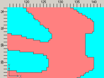
- Slopes and curves must be modelled by (replayed with) stairs (with line segments parallel to coordinate axes)
- Grouping of polylines by materials (thermal conductances)
either by equal layer number
or by equal line type
or by equal line colour.
(if some materials list shall be applied, stick to the naming convention chosen) - Grouping of polylines to generate component groups (if required)
either by equal layer number
or by equal line type
or by equal line colour. - Cleanup the drawing unused elements (e.g. apply "_purge" command in Acad).
- During saving to DXF file request scaling in millimetres.
- During saving to DXF file request the smallest number of decimal digits sufficient to represent coordinates precisely.
Editing of existing DXF file
- Draw over the CAD picture with polylines.
- Slopes and curves must be modelled by (replayed with) stairs (with line segments parallel to coordinate axes)
- Group polylines by materials.
- Group polylines to create component groups also (optional).
Remark: The order in which polylines are stored in (and thus also imported from) DXF file does not follow the order they have been input within CAD application. Due to the fact, that elements imported will follow the order of polylines as they are stored within the DXF file, we advise you not to use element (nor polyline) overlapping! If necessary you will make the use of reordering functions (promote or relegate) of elements to reach needed overlapping effects.
Remark: Different line ending conventions shall be tolerated within import: Windows (CR LF) - Macintosh (CR) - Unix (LF).
See also: Import of DXF file