The Building Component
 The
model of a building component is, generally put, built up with rectangular,
possibly overlapping,
elements. The term "component" need not have to be associated with typical
architectural or engineering meaning of building assemblies. The "component"
might resemble an excerpt from the building assembly containing one or more
building components in its typical meaning - like ceiling junction, window frame
connection etc..
The
model of a building component is, generally put, built up with rectangular,
possibly overlapping,
elements. The term "component" need not have to be associated with typical
architectural or engineering meaning of building assemblies. The "component"
might resemble an excerpt from the building assembly containing one or more
building components in its typical meaning - like ceiling junction, window frame
connection etc..
Within that application the term "component" does simply mean the ordered sequence of input elements composing some arbitrary object. The convenient input principle inherent to AnTherm - element overlapping - can facilitate construction input considerably if employed properly.
Groups
The construction to be simulated might contain some repeatedly appearing details. The input branch provides the notion of such details by groping them together (by unique group names) providing the method of quick selection, translation, rotation (by multiple of 90°) and mirroring (at axes parallel planes).
The ability to compose any construction from groups is provided as an additional helpful method significantly simplifying the input process.
Three dimensional constructions
The input of three dimensional components follows same rules as those for two dimensions.
3D Layered Model
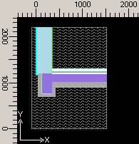
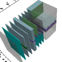 Three-dimensional
objects are modelled as a "sandwich" of parallel layers. Each layer is composed
of one or more elements. The elements of layers are entered to form a
two-dimensional description (x and y axes), or section, normal to the direction
chosen for layer depth (z axis).
Three-dimensional
objects are modelled as a "sandwich" of parallel layers. Each layer is composed
of one or more elements. The elements of layers are entered to form a
two-dimensional description (x and y axes), or section, normal to the direction
chosen for layer depth (z axis).
The thickness of a particular layer is defined by the depth for which a given section is a valid description of the structure. In other words, a separate layer must be specified for every change in cross-section when working through the layers of a particular model.
This should be taken into consideration from the very beginning in the form of orientation sketches showing the number of layers (x/y sections) which will be needed in the z direction.
Objects for which a two-dimensional analysis will suffice are modelled as an x-y section and evaluated per meter in the z direction. A dimensioned orientation sketch should include the origin which will be used for x and y coordinate input (an origin position along a component surface is usually the clearest solution).
See also: Project types: Layered 3D Project
3D Model
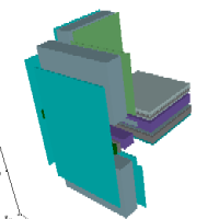 The
3D Model is created by entering arbitrary triples of coordinates. The
component's geometry is therefore described by input of ashlars.
The
3D Model is created by entering arbitrary triples of coordinates. The
component's geometry is therefore described by input of ashlars.
The resulting final 3D project is a sequence of such ashlars. The order of
ashlars is significant in that ashlars (i.e. three dimensional elements) sharing
same regions overlap, and those entered later hollow the properties of the
others - by the same overlapping principle as with
two dimensional rectangles.
See also: Elements of a component, Overlapping of elements, Project types