Generating the Model - Input
The program is called up with the Start-Menu Start→Programs→AnTherm→AnTherm, whereupon the default screen configuration appears.
From the main menu select File→New→2D Project. In the Description window enter some text information identifying the current project, e.g.
TUTORIAL - 2-dimensional: Reinforced concrete slab with masonry bearing wall on girder over carport (+ exterior insulation and electric heating cable assembly embedded in concrete floor topping). |
Note: Whatever text is typed here will be included at the head of program printouts (model documentation and numeric results). This screen can be accessed from the main window at any time by selecting View→Windows→Description.
Make sure Element input windows are open. There shall be at least Elements2D and ElementsBrowser widows already open now. If not, go into View-Menu and select View→Primary Edit Windows.
You can close the Elements 3D and Layer Browser window if displayed, by clicking on X at its top-right corner, since those windows are not being referenced in this tutorial.
The first element to be entered is the exterior space. On the ElementsBrowser window click New button. The element Edit window ( a Box Editor) shall reveal and a new, empty element shall list in the elements' list.
The boundaries of element 1 shall demarcate the full extent of the model with
X_1: -100 X_2: 1525
Y_1:    0 Y_2: 2200
- Start entering the coordinates by entering -100 for x1 first.
- Then press TAB-key to move the input focus to x2.
- Enter 1525 for x2 and TAB to next field, which is y1.
- Enter 0 for y1 and TAB to y2.
- Enter 2200 for y2 and confirm again with TAB.
Having now the focus in the "Box Type" field press arrow-down key to select "Space Box" as the type of this element (or either use the mouse to select the requested type).
Now TAB twice (skipping the Group entry for now) to move the input focus into "Surface Name" field. Enter "exterior surface" and TAB to its alpha value. Enter 25 and confirm the entry with the TAB again.
Name the room with "exterior" which will be later used to setup the temperature for this boundary. Confirm with TAB.
Once these entries are confirmed, element 1 is complete and the program is ready for input of the next element.
Now it would be worthwhile to re-scale the control graph for a better view of the component during input of successive elements: press Fit on the Element2D window and let the application redraw the graph.
Note to earlier WAEBRU users: As opposite to Waebru, AnTherm's Element 2D View does always show all elements of the one (and within the 2D model the only) layer. There is no such option to select the object display level to aggregate. Naming of groups and grouping is done directly to each element.
Before setting out to build up the material component, some thought should be given to the sequence of element input so as to best utilise the advantages of element overlapping. To illustrate this principle, the demonstration example described here has been organised into construction parts of predominantly parallel material layers. This simplifies coordinate input substantially.
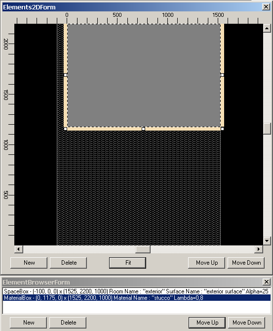
The first part of the model to be entered is the wall structure. An "onion skin" sequence begins at the outermost layer (stucco) with the second element:
X_1:    0
X_2: 1525
Y_1: 1175
Y_2: 2200
On the ElementsBrowser window click New button again. The element Edit window (the Box Editor) shall reveal and a new, empty element shall list in the elements' list next to the one entered before.
Enter the coordinates and confirm each entry with a TAB key as before. Using arrow keys while the focus is at the Box Type select "Material Box".
TAB to Material Name and enter stucco.
TAB to Lambda field and enter 0.8.
Note: While using international features windows provides you with country specific setting for decimal comma. This shall allow you to use numeric pad of your keyboard for entering number correctly. Please observe, that entering 0,8 (with comma instead of dot) might result in 08 if your setting of current operating system locale (typically Regional Setting of the System's Control Panel) defines different character (for example a dot) for decimal comma. The opposite might also be valid (e.g. german system use comma - the , character) for decimal comma. If the system is set up properly for your country, the numeric pad's comma will provide the right character to the input.
The control graph should now look like this:
To insert next new element use the context menu available to the Box Editor. Over the Box Editor click the right mouse button to reveal the Edit context menu. Select Add→Append.
The next element is the masonry wall, which overlaps - and thereby displaces - all but a thin strip of stucco (25 mm to the left and bottom):
X_1:   25
X_2: 1525
Y_1: 1200
Y_2: 2200
Box type: Material Box
Material name: Masonry wall
Lambda: 0.164
TAB to x1 and proceed with entering the data as before.
The interior plaster, the fourth element, delineates the right side of the masonry.
Instead of using New on ElementsBrowser or the context
menue's Add→Append sequence to add that next element to the list use
"Duplicate" on the Box Editor window. Since you have just TABbed to it
and it is visible marked as focused, simply press ENTER to execute the Duplicate
operation.
Here, only one coordinate of the set still visible from element 3 needs to be
adjusted to leave 200 mm of masonry thickness:
X_1:  325
X_2: 1525
Y_1: 1200
Y_2: 2200
Box type: Material Box
Material name: Interior plaster
Lambda: 0.7
TAB to x1 and proceed with entering the data as before.
When you confirm the entry and TAB to "Duplicate" press ENTER receiving again a copy of the lately active (selected) element. This simplifies the input to just the need of changing the things which are different for the new element and also leaves your hand off the mouse.
The next new element is the "kernel" of this part of the aggregate: the interior space overlapping all but the total wall thickness (with extended strip of stucco) of the material entered thus far:
X_1:  345
X_2: 1525
Y_1: 1200
Y_2: 2200
Box type: Space Box
Surface name: interior surface
Alpha: 6
Room name: interior
Create new element, TAB to x1 (if needed) and proceed with entering the data as before.
The last element edited is shown selected in the ElementsBrowser window. Holding the control-key click over the line with that selected element to deselect it. The selection mark shall disappear.
The control graph should now display the following figure of the standard masonry construction:
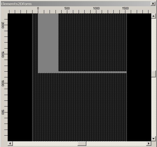
Note: The illustration above shows only the silhouette of the component in its current state.
The second part of the construction to be entered is the insulated girder, followed by the concrete floor slab with its exterior insulation. The final part of input covers the interior floor construction over the slab. These sequences are covered in the section on Completing the Component further on in this tutorial.
Continue reading with "Completing the Tables" ...