Fine-Grid parameter (dialog)
 The fine-grid subdivides the model into small cells which are then used to
solve the thermal equations during simulation. Creation of the fine-grid is
controlled via fine-grid parameters. Values offered by default have been preset
in such manner, that for most usual cases none of them needs to be adjusted.
The fine-grid subdivides the model into small cells which are then used to
solve the thermal equations during simulation. Creation of the fine-grid is
controlled via fine-grid parameters. Values offered by default have been preset
in such manner, that for most usual cases none of them needs to be adjusted.
Settings of the fine-grid process directly influence the size of the equitation system to be solved - the more detailed fine grid will create larger, eventually more complex, system of equations with higher number of cells to be balanced - that number is shown within the headings of evaluation reports.
Important: Very fine and detailed gridding (discretization) does not automatically ensure higher precision of results. Too detailed discretization might lead to unnecessary and inefficiently long calculations or even to results with less precision.
The most important setting of Start Step
shall typically correspond to the thickness of thinnest thermally significant
structure of the construction. As such higher subdivision of metal slabs is not
advisable.
The Maximum Step shall be significantly
raised when models of large dimensions of homogenous structures are considered.
The setting of Target Model Size is mostly used while benchmarking the precision of results, typically as last step during expertise process:
- coupling coefficients and the number of cells of a calculation shall be identified within its Coupling Coefficients report,
- for the purpose of additional calculation of results the Target Model Size will be requested at the half or at the double of the cell count reported earlier and the new calculation is executed,
- Coupling coefficients resulting from that second calculation (with half or double number of cells) are compared to the values received with the first calculation and respective precision criteria is validated then.
This final process of validation the precision of results conforms to the
requirements set by the Standard EN ISO 10211.
Important: This validation is independent from the check of
results precision provided within the respective
section of the Coupling Coefficients report (the
relative Close-Up Error).
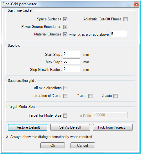
| Start Fine Grid at: | These are parameters defining starting criteria of the rasterizing process (creation of the fine grid) |
| Space Surfaces | Rasterizing will be initiated with its start step at each space surface and continue towards interior of the construction. |
| Adiabatic Cut-Off Planes | Rasterizing will be initiated with its
start step at each adiabatic cut-off plane
(adiabatic boundary) and continue towards interior of the
construction. (in earlier application versions also called "Cut-Off/Wonder" foil) |
| Power Source Boundaries | Rasterizing will be initiated with its start step at each boundary line of any power source. |
| Material Changes | Rasterizing will be initiated with its start step at boundary lines of different materials. An additional start criteria is defined the quotient of conductivity values (lambda quotient). |
| when λ, μ, ρ·c ratio above | Rasterizing will start with its
start step at boundary lines of
different materials (material change) if the ratio of conductivity
values (λ, μ, ρ·c values) of these materials is larger than the
magnitude entered here. If the change of λ, μ and ρ·c is not significant (quotient is smaller the the value entered here) rasterizing will continue with its normal coarsening process. Remark: To force the rasterizing to start at each material change boundary set this parameter <=1 Remark: The ratio (quotient) of conductivities of two materials is always calculated as the division of the larger value by the smaller one, thus it always results in ratios values >= 1. |
Step by: |
|
| Start Step | Rasterizing will start with this distance when
starting criteria is matched at
specific position. Remark: This is not the smallest step within the resulting fine grid - smaller structures can result relative position of elements and element dimensions also! |
| Max Step | The process of coarsening
the fine grid away from
start positions does not go beyond this value. If applicable rasterizing
will continue with this maximum value Remark: This value can be estimated automatically if target model size (number of fine grid cells) is chosen. |
| Step Growth Factor | At each further rasterizing step away from the position
where the
starting criteria has been matched
the step of fine grid (distance) is enlarged by that factor. Remark: ≥ 1.0 |
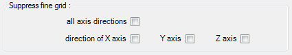
| Suppress fine grid in direction of X/Y/Z axis | Suppresses the process of fine grid generation in that
specific axis direction. Resulting fine grid is then identical to minimal
model grid. Remark: The application automatically detects homogenous dimension of the model (in that direction there will be no heat flow nor temperature gradients). If such direction is identified already within minimum grid, fine grid generation in this direction is automatically suppressed (regardless of the setting of the respective parameter here). |
Target Model Size: |
|
| Target for Model Size | When checked, one can request the target number of equations (cells). Rasterizer will then vary the maximum step to match the size at its best |
| # Cells | Rasterizer will vary the
maximum step by an iterative search
until it reaches the number fine grid cells within +/- 10% estimation range. Remark: If the target number cannot be reached sufficiently (i.e. maximum step could not be found satisfying other criteria), try to change the coarsening factor (step growth factor). Remark: „Max Step“ will be varied between „Start Step“ and full model extent. If there is no solution sufficiently matching the targeted criteria the most coarse fine grid (in the case the target number was too small) or the finest fine grid (if the target was too large) will be created. |
| Restore Default |
Reset all rasterizer settings to values provided in the application settings |
| Set As Default |
Current project setting will replace values provided in the application settings. |
| Pick from Project... |
Fine Grid settings will be loaded from another project. |
| Always show this dialog automatically when required | If checked the application will automatically reveal this dialog on each rasterizer run (in preparation of each calculation). |
Fine Grid parameters are saved to the project file.
Detailed description of gridding procedure
At first the application creates a "minimal grid" resulting from the overlapping of all elements. Overlapping of elements might result in removal of some elements if those are completely overlapped. The resulting model can be observed within the Elements3D window. The Modelling-Report will list all spaces, surfaces, power sources and materials actually used within final model.
 Then, the
application "visits" all boundaries of the minimal grid (which represents
elements entered) and identifies if they are one of:
Then, the
application "visits" all boundaries of the minimal grid (which represents
elements entered) and identifies if they are one of:
- Space surface (space boundary)
- change of material
- power source boundary
- adiabatic boundary
 Having
fine-grid parameters set, the application will start adding additional grid
planes in both directions away from these boundaries:
Having
fine-grid parameters set, the application will start adding additional grid
planes in both directions away from these boundaries:
- initially with starting step
- every next one in the distance enlarged by the step growth factor compared to the previous
- until the maximum step size has been reached, which will be used to subdivide the rest of the model.
 This
process is executed in all three Cartesian dimensions if not suppressed.
This
process is executed in all three Cartesian dimensions if not suppressed.
S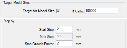 ee also: Solver,
Application settings,
Rasterizing
ee also: Solver,
Application settings,
Rasterizing